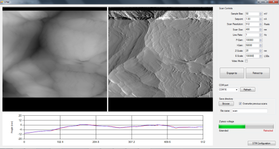
I finally got around to finishing up the Teensy software for my STM! The Teensy controls scanning, PI control of the Z-axis piezo, sigma-delta modulation of the scanner DAC outputs, and serial communications with a PC. I also wrote a C# program (screenshot above) that receives the serial data sent by the Teensy and displays the images line by line, and can set the scan parameters.
Here are the files:
There are simple libraries for the DAC8814 and LTC2623-16 included with Teensy software. Put them in your \Arduino\libraries folder. The PC software contains a .exe file and .exe.config file. Just put them in the same folder somewhere.
I’ll do a more detailed writeup on this later, but here’s a brief summary of how it works: the Teensy uses a timer to call a function at a regular time interval. This function increments the scan, performs PI calculations to update the Z axis, and performs sigma-delta modulation of the scanner DACs. Since the scanning probe is a (sharp, fragile) solid object, it’s velocity needs to be controlled at all times. If it moves too fast, it will likely crash into something, so the tip scans in a zig-zag pattern rather than a traditional raster (as in a CRT or SEM for example). Since the STM is always incrementing the scan at the same time interval, doing a slower scan will acquire more data. All data acquired between pixels is averaged, so you’ll get less noise in a slower scan. Once a line of the image has been scanned in one direction and re-scanned in the other direction, the Teeny sends the Z data and error signal data over USB.
If you need to invert the Z-axis signal, find the “#define INVERT_Z true” at the top of the Teensy code and change it to false.
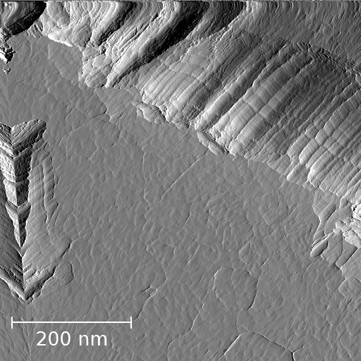
The PC software receives the data, does some basic processing, and adds it to the images on the screen. The left image is the topography (Z signal) and the right image is the error signal. The error signal looks like the gradient of the Z signal and has more high-frequency content. The topography data is displayed line by line in the graph at the bottom of the window. The red curve corresponds to the most recent scan line, and the blue curve is the same line scanned in the opposite direction. Ideally, these curves should be identical, but the agreement will never be perfect due to piezo hysteresis and things like that. If they don’t agree at all or show oscillations, try lowering the line rate, proportional and/or integral gains. For scans larger than ~500 nm or so, you’ll probably want to scan at ~0.5-2 Hz or so. For scans < 10 nm, you’ll want to go much faster to minimize thermal drift effect, ~10 Hz or more. You can also decrease the number of pixels to increase the speed.
Connect a LED to pin 0 on the Teensy. This is used to indicate serial communication is active. Connect another LED to pin 1. This one lights up when tunneling is achieved.
To use the software:
- Upload the code to the Teensy
- Turn the microscope on and start STM.exe
- Select the Teensy’s COM port from the list
- Do coarse approach until tunneling is achieved
- Press “Engage tip”. All this does at the moment is start the scan. You should see data coming in.
Images are saved as 16-bit, multi-page, uncompressed tiffs whenever a scan completes. You’ll want to use a program like Gwyddion to process the images, otherwise they’ll mostly just look gray. To view the error signal image (page 2 of the tiff), load the file into Gwyddion, click “Info” -> “Show Data Browser”, and check the box next to the error signal image.
There are still some issues in the PC software but it should work for the most part. It crashes on exiting, and I think I know what might be causing this but haven’t managed to fix it yet. I’ve also noticed that scan lines in the saved images are sometimes missing. CPU usage tends to be high when scanning at higher line rates. I’ll hopefully have a fix within a week or so and will update this post once I do.
If you find any other issues or have suggestions for improvements, please let me know in the comments!

