Piezo tube scanner

Got a tube scanner in the mail today! I paid $100 for it from Boston Piezo Optics, which seemed pretty good. If you want to get a tube from them, just make sure you get one that’s in stock as it will be much cheaper.

IMG_2264

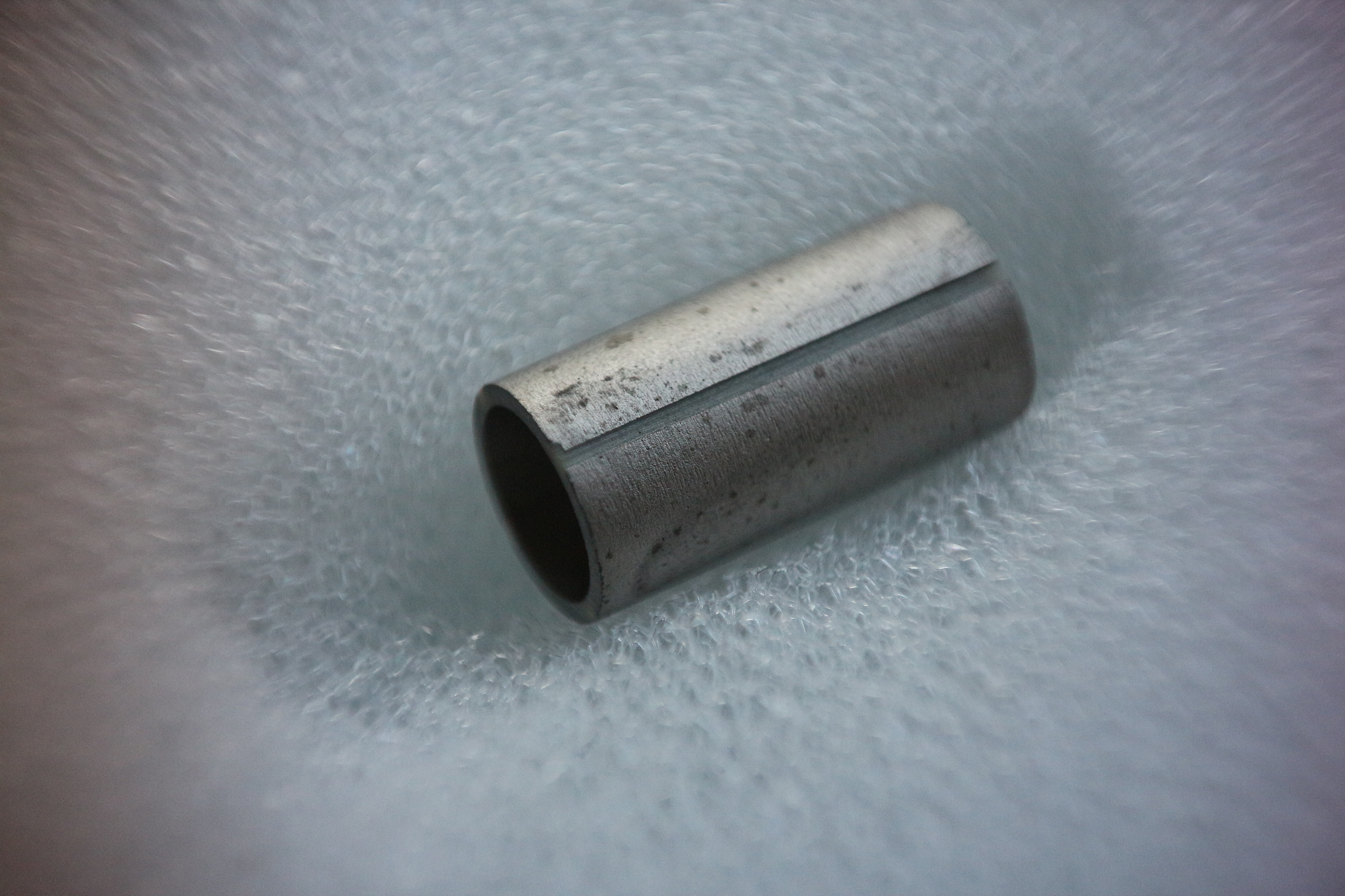
As I am more interested in high resolution than large scan ranges, I got a small, rigid tube with 0.25″ OD, 0.50″ length, and 0.025″ wall thickness. Dielectric material is PZT-5A. I’m going to design a new scan head for it, and include a stepper motor-driven coarse approach mechanism. Of course, i’ll also need to build a high-voltage amplifier to drive the tube scanner.

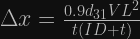
So how will this compare to the unimorph disc? My disc scanner has about 700 nm Z-travel and 1700 nm XY-travel, and about a 3.4 kHz resonant frequency. The Z-axis displacement Δz of a tube scanner can be calculated as follows [1]:

\Delta z=\frac{d_{31} V L}{t}

where L is the length of the scanner (0.50″), d31 is the piezoelectric constant (173 pm/V for PZT-5A), V is the applied voltage, and t is the wall thickness. This gives about 1 um for my tube with a 250 V range. We can also calculate XY displacement:

\Delta x=\frac{0.9d_{31} V L^2}{t(ID+t)}

which gives 1.7 um for my tube, so in terms of range, this tube is pretty similar to the unimorph disc, but requires much higher voltages. The big difference is in rigidity. This tube should have an extensional resonant frequency around ~30 kHz for a 1 g load [2], which should give a huge improvement in terms of scan speed and vibration tolerance.

[1] EBL Products has some useful information on tube scanners, including material properties and displacement formulae.

[2] Tetsuo Hanaguri has a spreadsheet to calculate scan tube resonant frequencies.

MLCC piezo actuators

The unimorph disk scanner is cheap, has low capacitance, and works at low voltages, making it great for a low-cost SPM. It does have one major disadvantage though: poor rigidity, especially in the Z-axis where it’s most important. This makes it highly vulnerable to vibrations and limits scan speed.

I’d like to replace the unimorph disk scanner in my STM with something more rigid. I thought about using multilayer ceramic capacitors (MLCCs) as actuators, given that they’re piezoelectric. A quick google search turned up one article on the subject (journal article is here).

The authors were able to get displacements of ~500 – 1000 nm from unpoled X7R capacitors (10 – 100 uF). These capacitance values are quite high and would severely limit scanning speed. A buzzer, for comparison, has a capacitance around 10 nF.

The displacement of MLCCs can be increased though by poling the ceramic dielectric. Piezoelectric ceramics are ferroelectric, and can be poled by heating above the Curie temperature, applying a voltage to align the ferroelectric domains, and letting it cool with the voltage still applied, locking the domains in their aligned orientation. I found another article describing this process being used on MLCCs to increase their sensitivity to applied forces.

Sounds simple enough, so I gave it a try on a 2.2 uF, 100 V, 1812-sized capacitor. I built up a simple 555-based boost converter on a breadboard to supply the 100 V poling voltage. The Curie temperature for BaTiO3 (the ceramic used in MLCCs) is only 120C, so I used a metal-can transistor as a tiny hot plate:

IMG_2244

I heated the transistor up to ~150C, applied 100 V to the capacitor and let it sit for about 2 hrs. I then turned off the heater, let it cool, then turned off the 100 V supply.

I used my STM to measure the displacement of both an unpoled and a poled actuator. I did this by sticking a small piece of copper tape the top of the actuator and applying the bias voltage (for tunneling) to the tape.

IMG_2247

I started scanning the copper tape surface and applied a small 10 Hz sine wave to the MLCC actuator from a function generator. Getting the displacement was then just a matter of reading off the amplitude from the trace/retrace plot during the scan (the Y-axis is in nm):

piezo_MLCC_poled_XXXXVrms_10p8Voffset

I measured about ~3 nm/V for the unpoled actuator (or 300 nm over its 100 V range), and ~8 nm/V (800 nm over it’s 100 V range) for the poled actuator. Not too bad, but I had hoped poling would make a bigger difference.

I’m not sure if I’ll build a new scanner using these actuators. They give very little displacement for a given capacitance, but do have the advantages of rigidity and low-cost. Using a smaller package, i.e. 0805 on the Z-axis is a possibility, but the required capacitance would still be fairly high. I might buy some piezo stacks instead, or look for a relatively cheap tube scanner.

That said, MLCC actuators do make for dirt-cheap, rigid nanopositioners, and you can always stack them to get displacements of several microns.