 I recently finished building a scanning tunneling microscope as a hobby project. The inspiration for this project came mainly from seeing John Alexander’s simple STM project some time ago. I’m a physics PhD student and although I work mainly with optical microscopes, I’ve had a few opportunities to use an atomic force microscope (AFM) and thought that building one would be a fun project. I ended up building an STM as it’s somewhat simpler and easily capable of atomic resolution imaging, but I do plan to add AFM capabilities to it at some point.

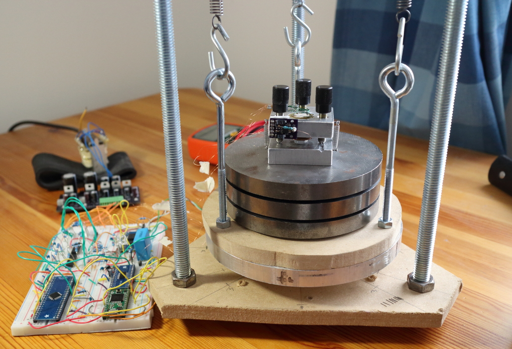
My STM uses the unimorph disk scanner invented by John Alexander. This type of scanner is much more sensitive and less rigid than the (much more expensive) piezo tube scanners typically used in scanning probe microscopes, but with low enough scanning voltages and decent vibration isolation I was able to achieve atomic resolution on graphite!
I’m currently working on improved schematics and laying out a PCB for this project, as the electronics are mostly on a breadboard at the moment.

I was planning on building this over Christmas brake, but I ran out of time and did not get to it. I have the PCBs required for the project if anyone is building this, I can send you the PCBs I had fabricated. Let me know if you are interested at bdb5454@psu.edu
Best – Baird Bankovic
LikeLike
Do you need to cool down or use a specific chamber to operate? If I use polypenco instead aluminium, would I get results, would be better or worst? Sorry but didn’t get it, the last disc is a magnet? Thank and my best congrats on this amazing, mind blowing project. Trully amazing!
LikeLike
Hi Rúben,
It works at room temperature, but you should use some sort of metal enclosure for shielding, otherwise the preamp/tip can pick up a lot of noise.
I haven’t tried using plastic for the scan head but I’m sure you could get it to work, though it will likely have some stability/drift issues. Plastics tend to have high thermal expansion coefficients compared to metals, and of course poor rigidity.
Yes, there’s a disc magnet mounted on the base of the STM (but insulated with a microscope coverslip) that I use for mounting samples. The bias wire is soldered to the magnet. I mount my samples on ferromagnetic discs (like a coin) so they can easily be swapped on the microscope.
Dan
LikeLike
Hi Dan, Fantastic work. I have been studying your work for awhile in order to make an attempt at building one myself. I had a question concerning your controlling Teensy code. It looks to me like you use the Increment scan function call to move the x,y position one position while taking taking one point of the PID and then accumulating a tabulated average of a set of z axis data collected for continuos steps. Please correct the following if this is incorrect for I may not understand fully your code, Would it be better if one ran the PID in a separate faster loop say 10x the scan loop. I am a little confused how you are staying locked in the PID loop for each scan step if you scan before you are necessarily under control. I would think that the PID loop should have more effective bandwidth than the scan speed. Woulldnt changing the PID to a faster call give you more precision?
I would appreciate it if help me clarify your code and my understanding on this subject.
Also,
have you done anymore work on the frequency AFM? I frequently check the site for your progress.
Again, great work. Thankyou.
Mike
LikeLike
Hi Mike,
Removing the scan stepping from the incrementScan() function wouldn’t allow it to run much faster. The point is to make the scanner movements in all axes as smooth as possible by updating all axes at a high rate. If the scan were incremented more slowly, the movements would be larger and less continuous, which actually makes it more difficult for the PID loop. The code essentially discretizes time into 30 us intervals. Since the scan is updated frequently, the step sizes are far too small for the tip to crash into anything between steps.
The AFM is still a work in progress, I just have a lot of time these days to work on this stuff, but it’s coming along slowly! Busy with the PhD!
Cheers,
Dan
LikeLike
can you help me? i’m really new to here, and i dont know what to buy. there are so many ads8517s! ADS8517IBDW, ADS8517IBPW, ADS8517IDW, ADS8517IBDW< ADS8517IBDWG4.. so many of them! are they different?? same with the other parts..
LikeLike
The datasheet for the ADS8517 will tell you the differences between these part numbers, but they all do the same thing and just have slightly different specs. They’ll all work fine, so just get whichever is cheapest.
LikeLike
Can you solder the pcb layout per hand?
LikeLike
Yup! If you haven’t done any SMD soldering before, check out Dave Jones’ tutorial: https://www.youtube.com/watch?v=b9FC9fAlfQE
LikeLike
In your Piezo drive circuit from january I understand U5A and U6A as an inverting stage to obtain the differential +/-X,Y signals to the piezos.
The other four U5C, U5D, U6C, U6D then drive the piezo segments themselves.
My Question is this: Why are all of these first order lag circuits? I would expect simple amplifiers to suffice to drive the transducers. Why is it that I am missing? I expect the drive signals to be perhaps a ramp voltage applied to the X and a triangle pattern applied to the Y to obtain the raster patter,
If you have a free moment could you explain why first order lag circuits are necessary as opposed to a simple gain stage to drive the piezo disks?
Did the analog Z feedback yield atomic resolution? I see you switched to an 16bit digital ADC and digital control in your most recent iteration. How successful was your analog feedback method
LikeLike
The capacitors in the op-amp feedback loops are just there for a bit of extra filtering, but aren’t necessary for the analog feedback circuit. However, in my digital feedback design I’m using sigma-delta modulation to increase the resolution of the 16-bit DACs to 20-bit, i.e. PWM-ing the outputs between LSBs. The op-amp filters are necessary in this case to average out the PWM switching.
I was never able to get atomic resolution images in constant current operation with analog feedback for some reason, but had no problem getting atomic resolution in constant height mode. It might be that I couldn’t set the integral gain high enough without causing the feedback to oscillate. Atomic scans need to be done quickly, requiring high gain for constant current mode. In my analog circuit I had no logarithmic correction for the tunneling current signal, so that’s probably why. I added this using a lookup table in the digital design and it really helped stabilize the feedback at higher scan speeds.
You could of course just add a log-amp to the analog feedback to get similar performance. There are examples of SPM at video rates with both analog and digital feedback, so I don’t think either one really offers a performance advantage. I switched to digital because it requires less hardware.
LikeLike
Most defiantly thanks for the response. I have been going through the steps to see if Z control with a stack piezo actuator intentioned for positioning of optics is feasible before making any purchases, it should do it no problem albiet at a higher actuating voltage.
Another question, speaking of reducing hardware what was your motivation for using a Current DAC with external I-to-V stage as opposed to perhaps a Voltage DAC feeding a gain stage?
Your implementation provides a gain of two correct? Which I believe is common for most Voltage output DACs as well.
LikeLike
I used the current DAC because it has much lower noise than any 16-bit voltage DAC I could find. The noise is essentially just the noise of its internal resistor ladder, however this does mean adding external op-amps is necessary. The low noise is what makes it possible to increase the resolution using sigma-delta modulation.
Yes, the second op-amp connected to each DAC channel provides a gain of two and shifts the output range to bipolar by subtracting the 10V reference.
LikeLike
Hi daniel,
your works are great!
i have one question
which resistor did you use in your breadboard?
1/4w? 1/8w? and does the accuracy(?) grade matter? such as 1%, 5%..
LikeLike
I believe they are all 1/4 watt. Since the supply is 15V, maximum power dissipation for a 10k resistor in the circuit will be only V^2/R = 15^2/10k = 22.5 mW. You can use smaller values to get slightly lower noise. Accuracy is not really important, and 1% resistors are so cheap I’d just use those.
LikeLike
in this page do what do you mean by ±15v and 3.3v and +5v?
you mean dc 15v? or ac 15v? and the other things too
and what amperage are they? is the amperage important?
LikeLike
I mean that the circuit requires +15V, -15V, +3.3V and +5V supplies. All DC. Current draw is somewhere in the low hundreds of milliamps (I didn’t measure it). I’m using standard linear regs like the 7815, 7915, 7805 etc.
LikeLike
how do you think, would smps be nice?
i have 3.3v smps adaptor(ac 220v to dc 3.3v) and 15v,5v smps adaptor.
would smps make too much noise? would it matter much?
LikeLike
I think it would matter a lot and the noise would definitely be a problem unless (maybe) you implemented some heavy filtering. SMPS would be fine to power the digital stuff, i.e. Teensy. The analog power supplies must have very low noise, and linear regulators are the simplest way to achieve this.
LikeLike
When do you think you’re going to write a post about programs?
I’m not really good at it as i’m not a good programmer. it’s very difficult 😦 but i’m studying it hard 😀
LikeLike
I’m not a great programmer either, which is part of why I haven’t posted any code yet. It’s just too messy right now 😛
I’ll try and post it sometime in the next few weeks.
LikeLike
Hello, I found very interesting results with the STM. I am university in Physics in Brazil. I was interested in reading their work. I would like to ask some questions about it. Do you own any e-mail contact? Because I want to build one until the beginning of 2016 to conduct small research. Thanks for attention.
LikeLike
Hi Nicolas,
You can email me at daniel (dot) berard (at) mail (dot) mcgill (dot) ca. Good luck with your build and feel free to email me with any questions.
LikeLike
I’d like to have a 40-min presentation about a home made STM, using your ultimate useful data. Do you think 40-min would be enough for such a presentation ?
Thanks
LikeLike
40 minutes is plenty, depending on how much detail you want to go into of course. Are you building an STM?
LikeLike
Thanks for your reply. No, I’m not building one in near future! But I should give a Talk as a part of Modern microscopical methods Lab.
Guess I won’t give too much details.
LikeLike
Hello, your results and craftmanship, the leverage between means and ends is astouding. It is hard to believe that so much can be done at such a ridiculous cost. Do you think it’s possible to extend your design to make electron beam lithography as in http://en.wikipedia.org/wiki/Electron-beam_lithography#New_frontiers_in_electron-beam_lithography? Wouldn’t it be fantastic? I know computer architecture from NP junctions up to distributed systems software but how satisfying it wouldn’t be to think one can be in his basement competitive with those sophisticated factories in asia an elsewhere!
LikeLike
That’s really interesting, thanks! I’ll look into it, although it would require a vacuum system.
LikeLike