Circuit overview
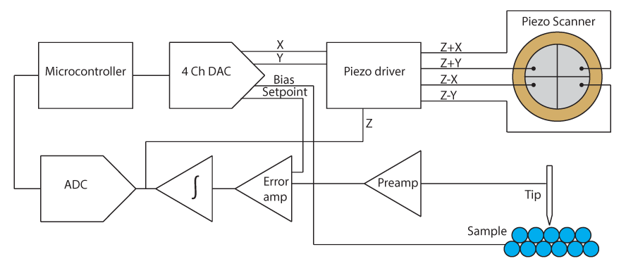
A DC bias voltage is applied to the sample, causing electrons to tunnel across the gap between the tip and the sample when they are brought close enough together (<1 nm). This current is measured by a preamplifier, which outputs a voltage proportional to the tunneling current. This voltage is compared to a setpoint voltage by an instrumentation amplifier (called the error amplifier), whose output is equal to the difference between the two. The error signal is fed into an integrator, whose output ramps up or down at a rate which depends on the error signal. This generates the Z-axis signal for the scanner. The X and Y scanning signals, as well as the sample bias and setpoint voltages, are generated by a 4-channel 16-bit DAC. The tunneling current or Z-axis piezo signals can be read by a 16-bit ADC and are used to construct the image. A Teensy 3.1 controls scanning and data acquisition. The teensy sends data to a computer over USB where it is used to generate an image. The design at the moment is a bit crude. I’m currently working on designing a proper PCB for this thing, and will post updated schematics when that’s done.
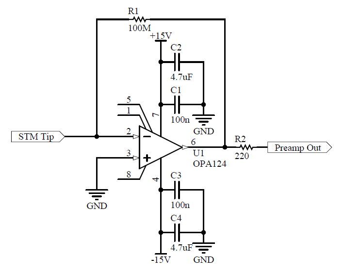
Tunneling current preamplifier
The preamplifier is an OPA124 op-amp with a 100 MΩ feedback resistor configured as a transimpedance amplifier. The output voltage of the amplifier is simply the tunneling current multiplied by the value of the feedback resistor. This allows it to measure currents up to 100 nA. I chose the OPA124 for it’s low input bias current and reasonably low noise. It’s important that the input bias current is significantly less than the tunneling current, or the measurement will be inaccurate. Some op-amps have input bias currents in the nA range, which is higher than the typical tunneling current, so avoid those! The OPA627 also seems to be a popular choice for STM. OPA128 and OPA129 look like they would also work well.
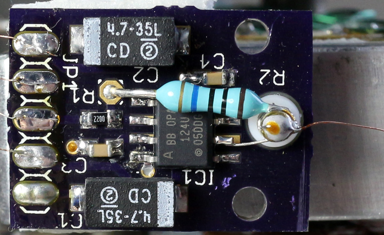
To minimize noise pickup, I’ve built the preamp on its own small PCB and mounted it directly on the STM head. A short 40 AWG wire connects the STM tip to the preamp input. I place a metal can over the STM during scanning to shield the tip and preamp. Without the shield, the images produced by the STM are dominated by 60 Hz noise pickup.
Since the tunneling current is pretty small, care needs to taken to avoid leakage currents. Currents leaking into the op-amp input node will be summed with the tunneling current by the preamp and create a significant offset voltage error. The FR4 and PCB silkscreen materials are not great insulators in this case, so I’ve insulated the input node with a teflon standoff and bent the op-amp’s input pin off the surface of the board. Alternatively, you could use a guard trace surrounding the input node.
Feedback loop
I chose to implement an analog rather than digital feedback loop, mainly because it was cheaper. The piezo needs to have a high enough dynamic range in the Z-axis to be able to resolve atomic-scale features as well as tolerate some thermal drift. I’m using the very low noise OPA2227 and INA114 in the feedback loop so the signal-to-noise ratio is quite good. I would need to use an expensive 20-bit DAC such as the AD5791 to achieve similar performance using a digital feedback loop, or operate the scanner with a reduced Z-axis travel range.
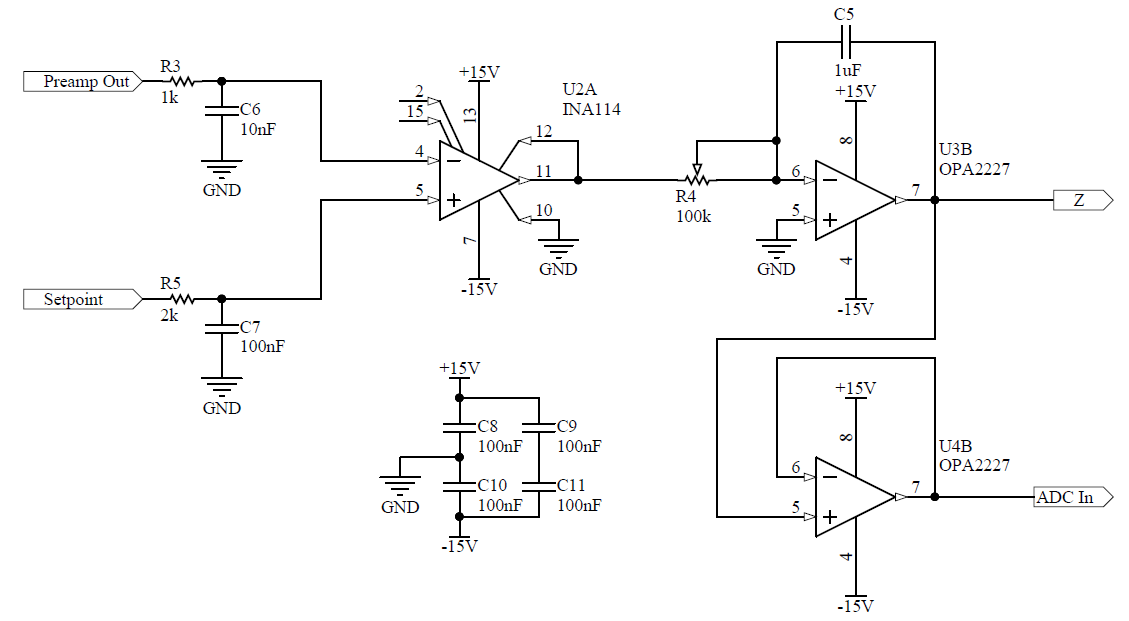
The tunneling current signal is compared to the setpoint (generated by the 4-channel DAC) using an INA114 instrumentation amplifier configured for unity gain. The signal then goes to an integrator, implemented using an OPA2227 with a 1 uF polypropylene feedback capacitor. The integral gain is controlled with a potentiometer. The output of the integrator, after being combined with the X and Y signals at the piezo driver, is used to drive the Z-axis of the scanner.
The tunneling current depends exponentially on the tip-sample distance, but I haven’t bothered to implement a logarithmic amplifier in the feedback loop to linearize this signal. This means that the loop will respond differently for large deviations from the setpoint depending on the sign of the error signal. This actually helps to protect the tip from crashing into the sample surface since the tunneling current increases exponentially when the tip approaches the surface, and the feedback loop applies a large correction to the Z-piezo to retract it. I may add a log amp later on to see if it improves the feedback loop performance.
Piezo driver
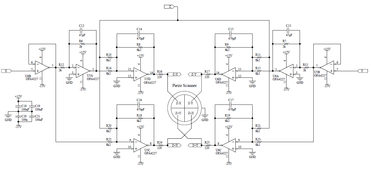
STM’s typically use fairly large voltages (typically around ±200 V) to drive the scanner. However, piezo buzzers like the one I’m using have relatively large travels at low voltages, so I’m using ±15 V supplies for the piezo driver. This gives a few microns of travel in all axes. I’m using a pair of OPA4227 quad op-amps to implement the piezo driver circuit shown below, which combines the X and Y scan signals from the DAC with the Z signal from the integrator to drive the 4 scanner electrodes. The Z signal is simply added to all 4 electrodes by the summing amplifiers. To obtain atomic resolution, I have to attenuate the X and Y scan signals by a factor of 10 by replacing the X and Y summing resistors (R14, R15, R22 and R23) in the piezo driver with larger values.
Data acquisition and scanning
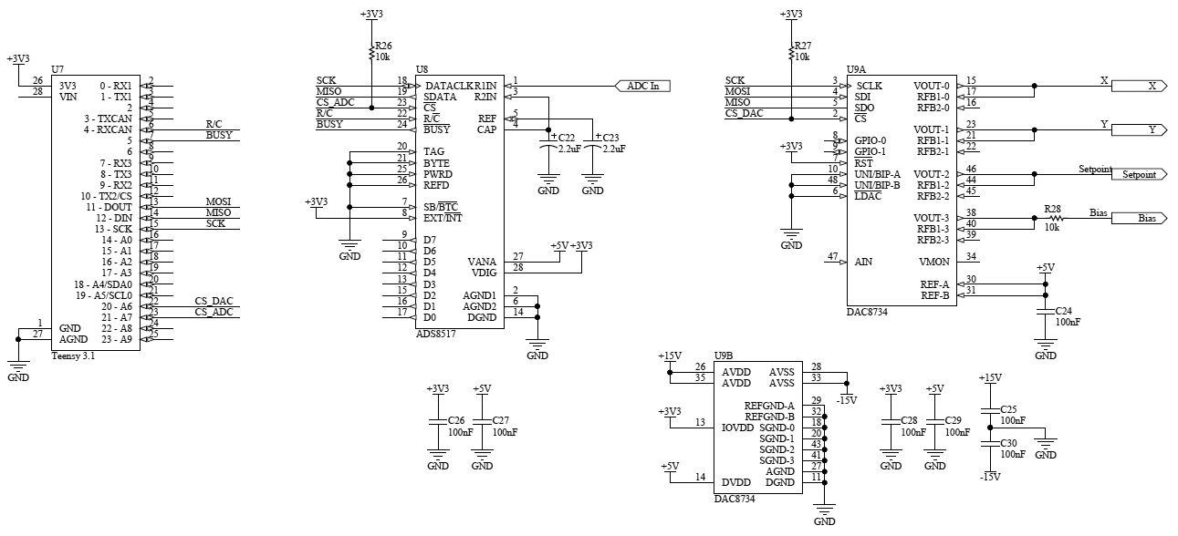
A DAC8734 16-bit 4-channel digital-to-analog converter generates the setpoint, bias, and XY scanning waveforms. An ADS8517 16-bit ADC measures the tunneling current or Z-axis piezo drive signal which is used to form an image of the sample surface. Scanning and data acquisition are controlled by a Teensy 3.1. The Teensy sends data to a laptop every time it scans a row of pixels. I’ve written a simple program that draws the image one line at a time on the screen as the data comes in from the STM, and also allows me to control the sample bias, setpoint, scan size, image resolution and scan speed from the computer.
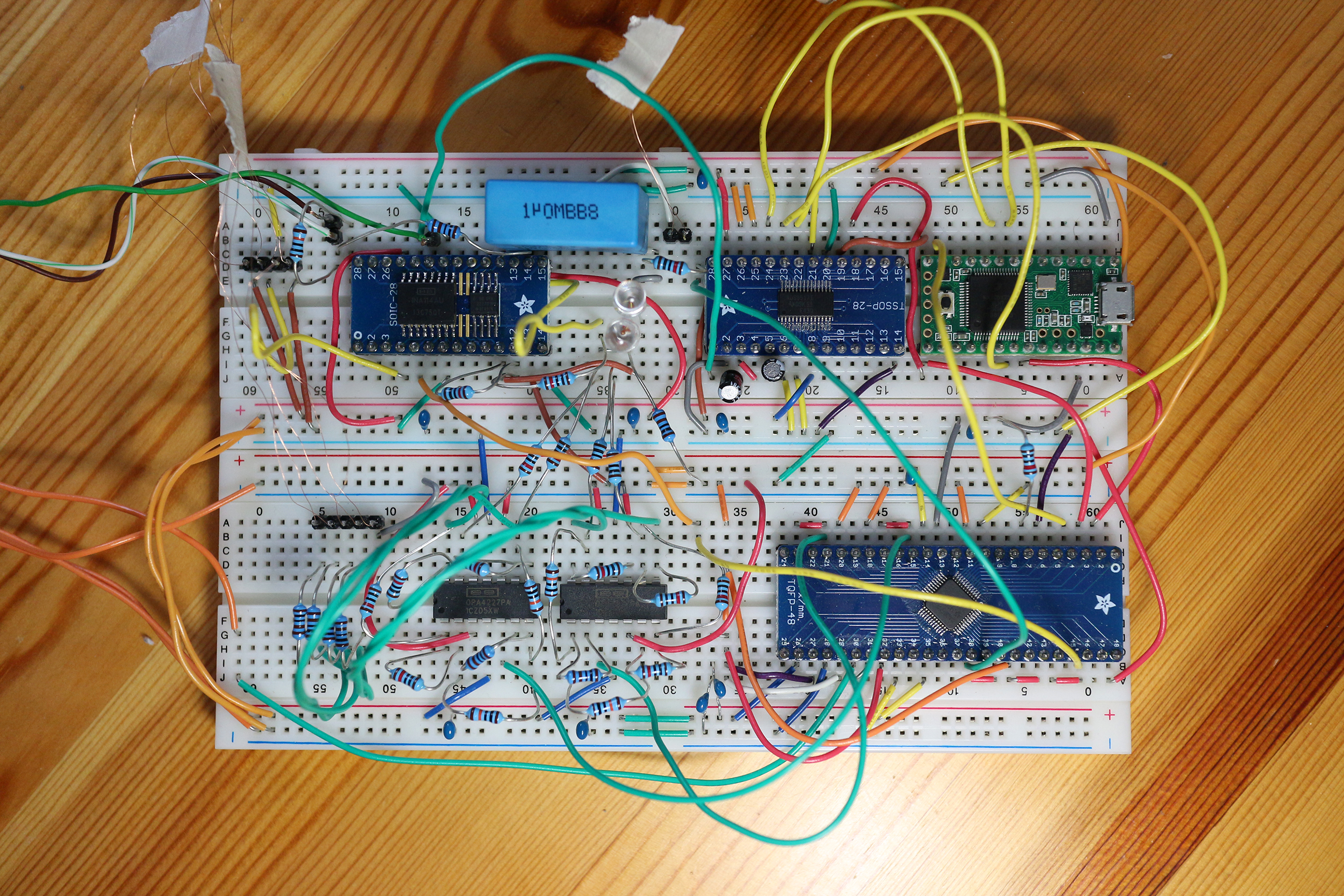
Here’s the current setup on a breadboard. I’m working on designing a PCB and will add updated schematics at some point.
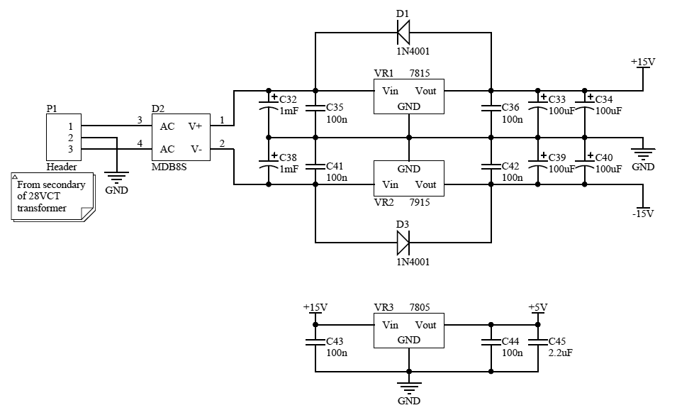
Power supply
I’m just using standard linear regulators and a center-tapped transformer to generate ±15 V supplies and a +5 V supply. The Teensy generates 3.3 V from an on-board regulator.