
Piezo Scanner
Piezoelectric actuators can achieve sub-nanometer positioning resolution, and are used in all scanning probe microscopes. Most make use of piezo tube actuators, and some use piezo stack actuators. It’s important that the actuator is rigid to minimize the effects of vibration on the tip-sample distance. Tube scanners tend to be more rigid than those made from stack actuators, but are not cheap. Either type of scanner will cost at least a couple hundred dollars, so I decided to make the “unimorph disk scanner” invented by John Alexander and used in his low-cost STM design. This scanner is based on a cheap piezo buzzer with one of the electrodes cut into quadrants, so that the single buzzer is used for XYZ motion. The STM tip mounts on a standoff glued to the buzzer. Wires are usually glued to the electrodes using a conductive epoxy, as excess heat from soldering can depolarize the piezo ceramic. I soldered mine anyway using a low temperature, and my actuator works fine, although it’s possible I might have depolarized parts of the ceramic.
I used this buzzer, which has a 20 mm diameter and 6.3 kHz resonant frequency. These things aren’t particularly rigid (especially with the standoff glued on) given that they’re designed to be used as speakers, so they won’t perform as well as a piezo tube scanner. I measured a lowest resonant frequency of 3.4 kHz for the assembled scanner. I was still able to achieve atomic resolution, but I might switch to a smaller scanner with a higher resonant frequency in the future to see if it improves performance.
The STM tip mounts in a pin socket for quick and easy exchanging. The socket is glued into a hole drilled in an aluminum standoff. The standoff is glued to a small sapphire disk, which is glued to the buzzer’s brass electrode for electrical insulation. It’s important to make sure that no glue connects the aluminum tube (which is electrically connected to the STM tip) directly to the brass electrode (which is grounded), in order to prevent current leakage from the tip to ground. Sapphire is a much better insulator than the glue, which is important since we are dealing with very small current signals. Glass or ceramic would also be good materials to use here, but I would avoid plastics in the scanner construction.
The image below is a top view of the STM with the scanner mounted, showing the top piezo electrode cut into quadrants. I just used an x-acto to cut the electrode, while being careful not to damage the piezoelectric ceramic too much.
Buzzers have a much larger displacement per applied volt than tube scanners (somewhere around ~160 nm/V in the case of John Alexander’s buzzer scanner and ~10 nm/V for a tube scanner in the Z-direction), which means that they must be driven with much lower voltages in order to achieve the same resolution. Tube scanner typically operate with around ~±200 V supplies, whereas I run my scanner with ±15 V supplies. The resolution should ideally be ~0.01 nm or better in the Z-direction, which corresponds to 62.5 μV for a scanner with 160 nm/V displacement. This is no problem for low-noise op-amps like the OPA4227, and ±15 V supplies give plenty of travel range. Just keep in mind that the resolution of a 16-bit ADC with a ±10 V input range is 305 μV, so extra amplification (with a gain of at least 5) or a more precise ADC is necessary to achieve this kind of resolution in the constant-current imaging mode (i.e. the feedback loop is active). In constant-height mode (feedback loop disabled and image acquired by measuring the tunneling current), the preamp provides enough amplification for atomic resolution imaging.
Scan Head and Coarse Approach Mechanism
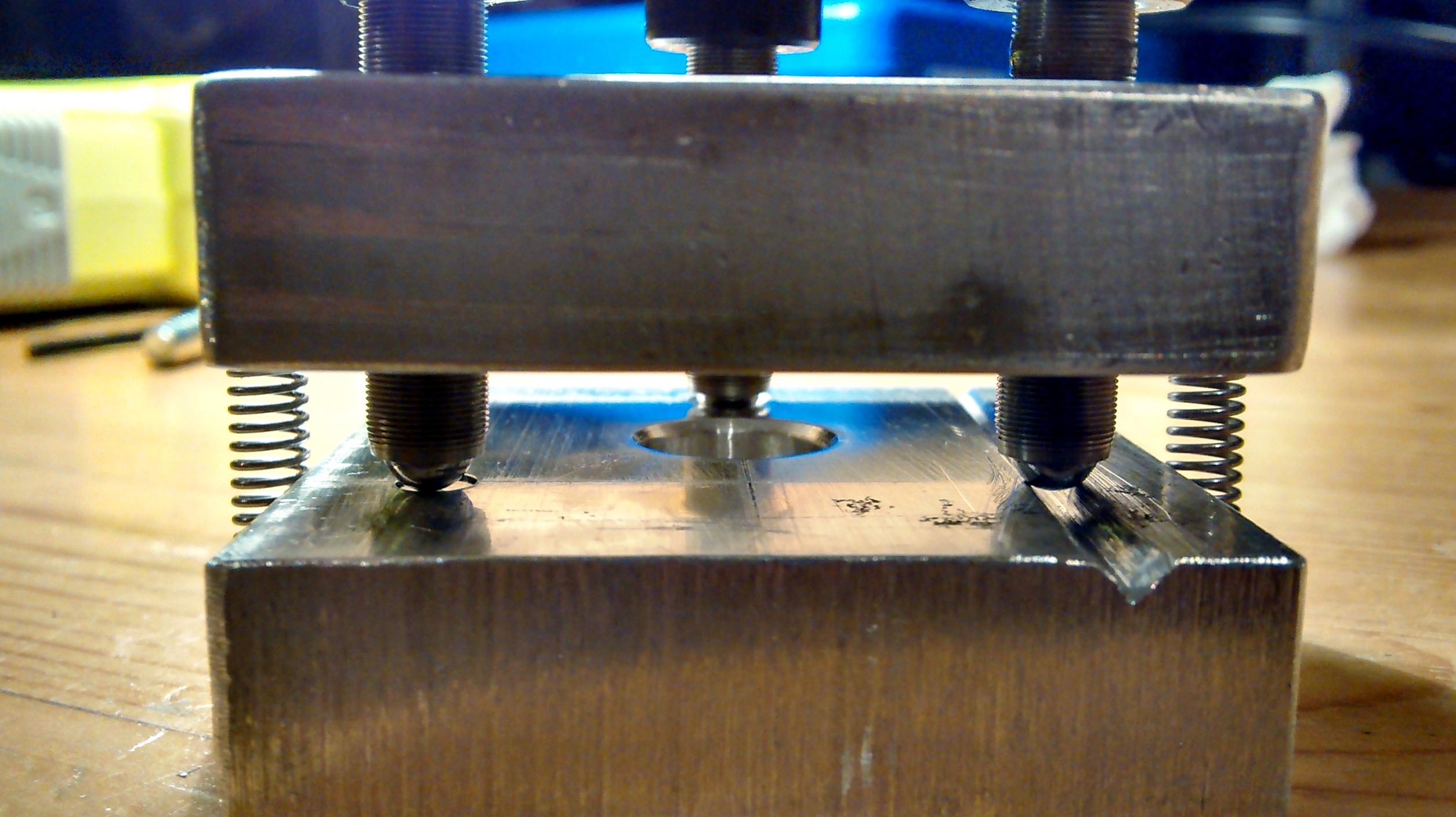
The STM scan head is made from two 2″ x 2″ x 1/2″ aluminum blocks connected by three 1/4″-80 precision adjustment screws. You can get the fine pitch screws along with brass threaded bushings from McMaster Carr. The aluminum parts were made with a hacksaw, drill press and file. The screws have ball tips that are kinematically coupled to the aluminum base. One ball tip mates with a cone (made with the point of a drill), one with a V-groove (made with a file) and one with a flat (I used a sapphire disk, but just using the flat surface of the aluminum would be fine). Dimensions are given below in mm [in].
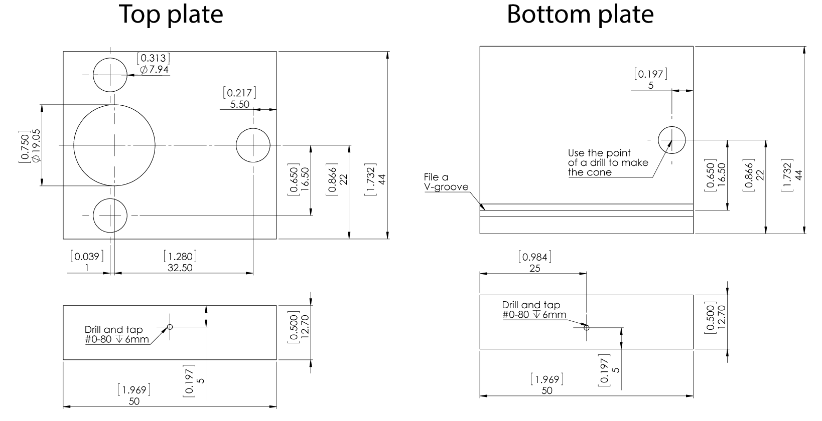
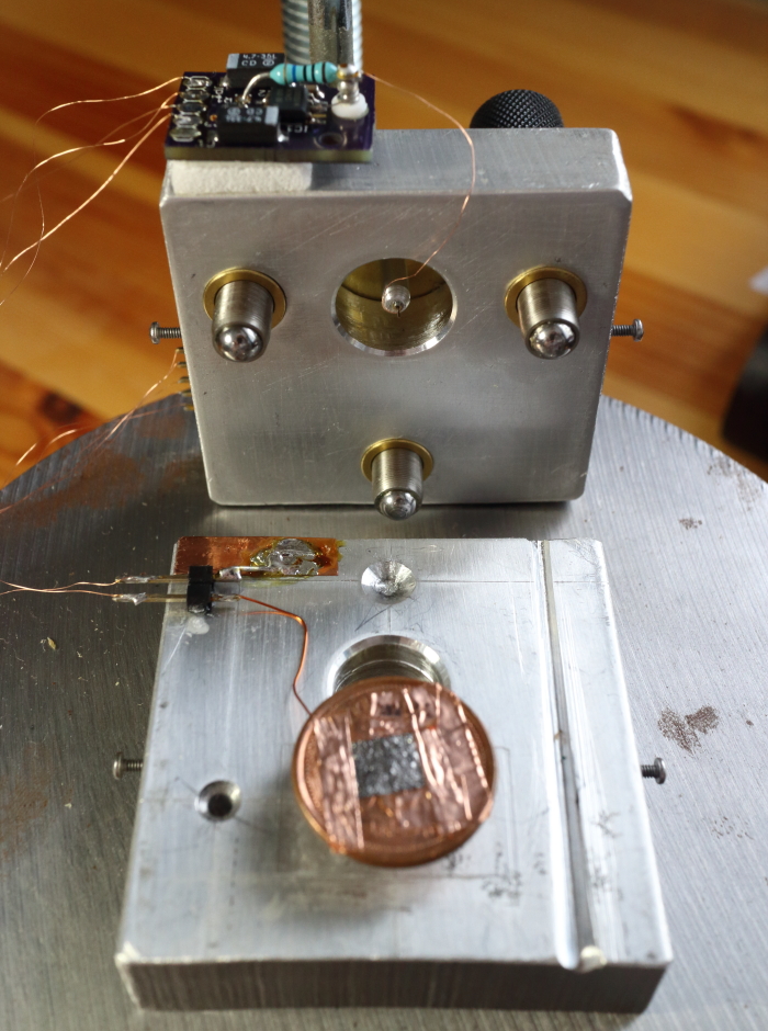
The precision adjustment screws are used to bring the tip and sample into tunneling distance at the beginning of an experiment. The feedback loop is running during this approach process, so the approach mechanism must be able to bring the tip close enough to the sample so that it is within the travel range of the scanner’s Z-axis (about 3 μm in this case). The precision adjustment screws are arranged in a tripod, where the two front screws are close to the scanner and are used as a coarse approach. The position of the scanner is offset by ~1 mm from the line connecting the two front screws, so the motion of the rear screw is reduced by a factor of about 30 and it provides finer adjustment. I start by using the front screws to bring the tip as close as I can to the sample without crashing it into the surface, and then slowly turn the rear screw until tunneling current is established. I’m doing this manually at the moment but plan to add a stepper motor to control the rear screw so that the approach process can be more automated, reducing the risk of crashing the tip during the approach. I just mount the sample to a penny with copper tape and stick it to a magnet mounted on the STM base. The sample bias wire is soldered to the nickel-plated magnet and is electrically insulated from the grounded base by a a piece of microscope cover glass. This allows quick and easy sample exchange.
Aluminum is not the greatest material for the STM body since it has a fairly large thermal expansion coefficient. Macor (a machinable ceramic) is probably the optimal material since it has a thermal expansion coefficient that is well matched to that of the piezo ceramic. Thermal expansion is not such a big deal though since it typically appears as a slope in the images and can easily be corrected for in post-processing. Thermal drift can sometimes be an issue after coarse approach, but after several minutes it tends to stabilize, and can usually operate for over 2 hours without drifting out of the scanner’s vertical travel range.

Pingback: ShareAHack.com | This DIY cheap STM microscope can actually see atoms
Pingback: Question about piezo crystals | Physics Forums - The Fusion of Science and Community
Pingback: Esoteric Actuators | Daily Hackers News
Pingback: Esoteric Actuators | Hackaday