Got a tube scanner in the mail today! I paid $100 for it from Boston Piezo Optics, which seemed pretty good. If you want to get a tube from them, just make sure you get one that’s in stock as it will be much cheaper.
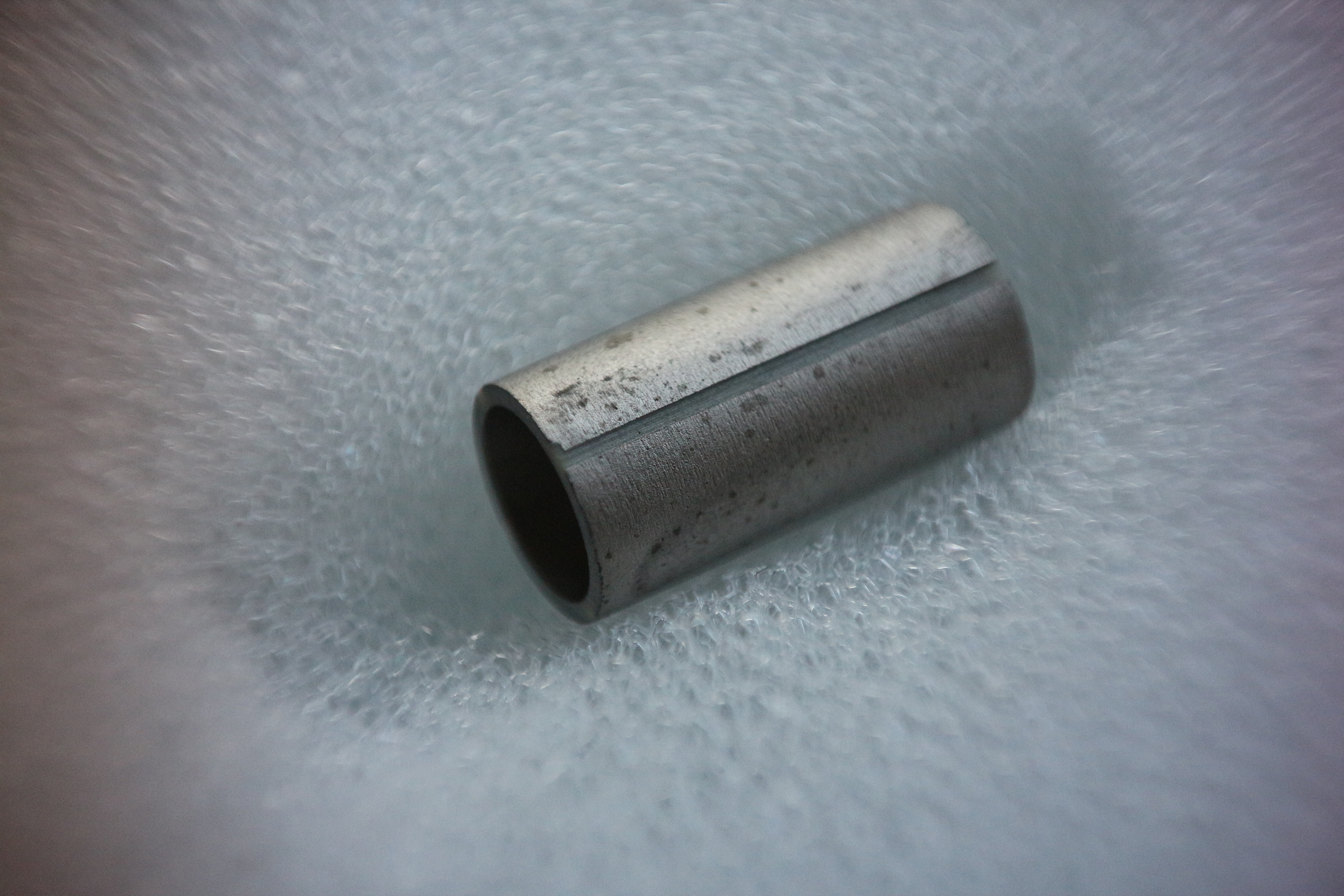
As I am more interested in high resolution than large scan ranges, I got a small, rigid tube with 0.25″ OD, 0.50″ length, and 0.025″ wall thickness. Dielectric material is PZT-5A. I’m going to design a new scan head for it, and include a stepper motor-driven coarse approach mechanism. Of course, i’ll also need to build a high-voltage amplifier to drive the tube scanner.
So how will this compare to the unimorph disc? My disc scanner has about 700 nm Z-travel and 1700 nm XY-travel, and about a 3.4 kHz resonant frequency. The Z-axis displacement Δz of a tube scanner can be calculated as follows [1]:

where L is the length of the scanner (0.50″), d31 is the piezoelectric constant (173 pm/V for PZT-5A), V is the applied voltage, and t is the wall thickness. This gives about 1 um for my tube with a 250 V range. We can also calculate XY displacement:
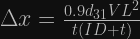
which gives 1.7 um for my tube, so in terms of range, this tube is pretty similar to the unimorph disc, but requires much higher voltages. The big difference is in rigidity. This tube should have an extensional resonant frequency around ~30 kHz for a 1 g load [2], which should give a huge improvement in terms of scan speed and vibration tolerance.
[1] EBL Products has some useful information on tube scanners, including material properties and displacement formulae.
[2] Tetsuo Hanaguri has a spreadsheet to calculate scan tube resonant frequencies.

Hi Dan!
This is a fascinating project. I’m starting a medium-project to build a low-cost AFM. I believe you mentioned that you were planning to add AFM capability to this project. Did you pursue that?
I think I’ve figured out a way to make a low-cost AFM probe, but I’m still thinking about how to do actuation. I’m thinking there need to be two stages: microsteppers that can move a significant distance and nanopositioners. For the nanopositioners, do you think a piezo tube scanner is the way to go, or would something more complicated with different drivers for each axis + flexures be necessary?
Thanks, and hope you’re doing well,
Lachlan
LikeLike
Hi Lachlan,
I did pursue adding AFM capability but that project has been on the back burner for a while. I did document a bit of it here: https://hackaday.io/project/5713-frequency-modulated-atomic-force-microscope
For the scanner, it really depends what scan range and speed you’re looking for. Piezo stacks with flexure motion amplifiers can get you into the ~100 um range but they have low resonant frequencies. Flexure-guided (but not amplified) stacks on the other hand can be very rigid and fast, but tend to have high capacitance compared to tube scanners. Tube scanners should be great too, for scan ranges in the ~1-10 um.
LikeLike
Hi Dan,
I apologize if you have already covered this, I’m pretty new to this, so there is a chance that I have missed it. Can you please show exactly how the tube scanner is incorporated into the scan head?
I know that you showed that you were working on a new scan head that would implement the tube scanner on September 13, 2015, and that you updated your original scan head to have a motorized coarse approach on November 8, 2015. But haven’t seen any updates past that.
Any and all insight is appreciated,
Nathan
LikeLike
Hi Nathan,
I never got around to completing that design, I got really busy with my PhD which I recently finished. I’m currently working on improved software but I do plan to build an AFM at some point using a similar design to the one I posted with the piezo tube.
I was going to glue ceramic washers to each end of the piezo tube for mounting to metal surfaces, while allowing wire(s) to pass through.
Cheers,
Dan
LikeLike
Thanks for the quick reply Dan, Congrats on completing your PhD!
I appreciate you giving me insight on how you were going to incorporate the piezo tube, but like I said in my previous comment, I am fairly new to this, so I will stick with the design that doesn’t incorperate the tube. Best to leave that until I get a bit more experience under my belt.
Last questions (hopefully). Does the length and diameter for the aluminum standoff that you use on the piezo scanner influence the scans or build in any way? obviously I don’t want it to be 2″ long, but is there a size that I should look for, also, is it better for it to be hollow or solid?
Last question, you mention using glue to hold several of the papers together, are you using a specific kind or just superglue?
Again, that you for being so helpful with all of this. I look forward to seeing how to continue to evolve this and the AFM as time goes on.
Kind regards,
Nathan
LikeLike
Thanks! Yeah I’d recommend starting with the disk scanner, that saves you having to build HV amplifiers and power supplies.
The mass of the aluminum standoff will affect the Z-axis resonant frequency of the scanner. The lighter it is, the better, and the higher the resonant frequency. This makes it more resistant to vibrations and able to respond faster. For this reason, a hollow tube will be a bit better.
The XY scan range is proportional to the length of the standoff. But the length and mass of the standoff will also affect the XY resonant frequency. Short/lighter is better in this regard. You can trade rigidity for increased scan range by using a longer standoff. I made mine 1/2″ long. If you want to increase scan range, you also have the option of using a larger piezo buzzer.
I used super glue for everything. Epoxies would work well too.
Cheers,
Dan
LikeLike
did you think about using one of this (or something like this):
https://skultrasonic.fr.aliexpress.com/store/group/Piezoelectric-Ceramic-Tube-Ring-Disc-shape/412290_211684876.html?spm=a2g0w.12010612.0.0.67596749wckXPy
LikeLike
None of those really look suitable for scanning unfortunately, you’d need a piezo tube or disc with quadrant electrodes, or a stage using piezo stacks. The scanner needs some way to flex or move in X, Y, and Z.
LikeLike
Sorry if this is a double post, my browser crashed and i´m not sure if the post was submitted or not:
Hi Dan,
i`m very impressed by what you have achieved already, really great work. Also, i appreciate your effort of writing everything down! Thanks to your blog, i wanna build a STM aswell 😉
I got a question to you regarding the control of the voltages applied to the piezo that hasnt been cleared up by the link you posted above (http://www.piezodrive.com/product-tubes.html). Take for instance the peizo tube you bought at boston piezo optics which has a maximum voltage rating of 250V, where you calculated a maximum deltaX of around 1µm (125V at on electrode and -125V at the opposite electrode supposedly). If i understood it correctly, if you want to use it as a scanner, you have to supply a voltage to x,y and z simultaniously. So is the value of 250V per axis or the total voltage that can be applied to the piezo? For instance, if you would want to scan along the x-axis and start at, WLOG, +x_max, +y_max for a given z elongation, would you apply 250V to the x axis and 250V to the y-axis and ramp Vx from 250V to -250V or do you have to consider something like the rms of Vx and Vy (and Vz)?
I hope you get my problem 😉
Best regards
Mat
LikeLike
Hi Mat,
It can actually handle a bit more than 250V. That link lists the AC depoling field for PZT-5A as 7 kV/cm RMS. This is the voltage that, when applied against the piezo’s poling direction, will depole the ceramic. The wall thickness of this tube is 0.025″ (0.0635 cm), so the maximum voltage would be 7 kV/cm * 0.0635 cm = 445V. This is the maximum voltage that can be applied across the wall of the tube.
Any voltage applied between the inner electrode (Z) and any outer electrode (X or Y) must not exceed 445V. This means that, if we use symmetric +- supplies, we are limited to +-222V supplies. If we apply +222V to the inner electrode and -222V to any outer electrode, then the voltage across the wall is 444V. It doesn’t matter if we apply -222V to one outer electrode or all of them, the voltage across the wall (or at least part of the wall) either way is 444V.
Hope that’s clear. Really we should use lower voltages to be safe, maybe +-175V or lower? The next challenge is to build amplifiers that can drive these voltages with ultra-low noise and don’t cost an arm and a leg… I’m looking at Linear Tech AN18, Fig. 9: http://cds.linear.com/docs/en/application-note/an18f.pdf
Cheers,
Dan
LikeLike
Hi Dan,
thank you for your fast reply, it answered my question and cleared things up. I already ordered one of the exact same piezos you are going to use, since i havent found any supplier here in germany, that offers piezos at that price!
Thank you for the application note. The amplifier shown there seems to be exactly what is needed here. I havent figured out yet how to generate the high voltage rails though (transform the power line`s 230V down, a dc-dc-boost converter, etc.) but i`ll definatelly stick around +-125 in the beginning.
I´ll probably set up a hackaday.io project about my attempt of a STM in the upcoming weeks and hopefully i can contribute anything useful to your project, since your blog has been extremly helpful to me already (regarding planing of the device, needed parts etc..)!
Best regards
Matthias
LikeLike
Cool, looking forward to seeing how it turns out!
As for the supplies, having low noise is absolutely crucial, so I’ll be using linear supplies. My plan is to use a commonly available 120V to 240V transformer to get close to +-170V supplies, which seems optimal for this piezo. Since you have 240V, just use a 240V to 240V isolation transformer (with dual secondaries or a center tap for ground). As for linear regulation, check this out: http://www.ti.com/lit/an/snva583/snva583.pdf
You can get low noise with switching regulators too, it just might take more effort/experimentation, and probably will cost more in the end since you don’t need a particularly large transformer either way. Check out this Jim Williams app note: http://cds.linear.com/docs/en/application-note/AN118fb.pdf
LikeLike
Hi Dan,
i`m very impressed by what you have achieved already, really great work. Also, i appreciate your effort of writing everything down! Thanks to your blog, i wanna build a STM aswell 😉
I got a question to you regarding the control of the voltages applied to the piezo that hasnt been cleared up by the link you posted above (http://www.piezodrive.com/product-tubes.html). Take for instance the peizo tube you bought at boston piezo optics which has a maximum voltage rating of 250V, where you calculated a maximum deltaX of around 1µm (125V at on electrode and -125V at the opposite electrode supposedly). If i understood it correctly, if you want to use it as a scanner, you have to supply a voltage to x,y and z simultaniously. So is the value of 250V per axis or the total voltage that can be applied to the piezo? For instance, if you would want to scan along the x-axis and start at, WLOG, +x_max, +y_max for a given z elongation, would you apply 250V to the x axis and 250V to the y-axis and ramp Vx from 250V to -250V or do you have to consider something like the rms of Vx and Vy (and Vz)?
I hope you get my problem 😉
Best regards
Mat
LikeLike
What is the difference between this tube and the piesoeletric buzzer with tip?
Can you explain more to us plesae?
LikeLike
Tube scanners like this are used in the majority of scanning probe microscopes. They work pretty much the same way as the unimorph disc: the tube has an inner electrode and an outer electrode, which is cut into quadrants. By controlling the voltages on these electrodes in the same way as with the unimorph disc, the tube can be made to bend (for XY scanning) or extend/contract longitudinally (for Z-motion). Here’s a reference with more info: http://www.piezodrive.com/product-tubes.html
LikeLike