The unimorph disk scanner is cheap, has low capacitance, and works at low voltages, making it great for a low-cost SPM. It does have one major disadvantage though: poor rigidity, especially in the Z-axis where it’s most important. This makes it highly vulnerable to vibrations and limits scan speed.
I’d like to replace the unimorph disk scanner in my STM with something more rigid. I thought about using multilayer ceramic capacitors (MLCCs) as actuators, given that they’re piezoelectric. A quick google search turned up one article on the subject (journal article is here).
The authors were able to get displacements of ~500 – 1000 nm from unpoled X7R capacitors (10 – 100 uF). These capacitance values are quite high and would severely limit scanning speed. A buzzer, for comparison, has a capacitance around 10 nF.
The displacement of MLCCs can be increased though by poling the ceramic dielectric. Piezoelectric ceramics are ferroelectric, and can be poled by heating above the Curie temperature, applying a voltage to align the ferroelectric domains, and letting it cool with the voltage still applied, locking the domains in their aligned orientation. I found another article describing this process being used on MLCCs to increase their sensitivity to applied forces.
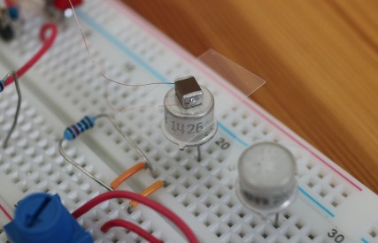
Sounds simple enough, so I gave it a try on a 2.2 uF, 100 V, 1812-sized capacitor. I built up a simple 555-based boost converter on a breadboard to supply the 100 V poling voltage. The Curie temperature for BaTiO3 (the ceramic used in MLCCs) is only 120C, so I used a metal-can transistor as a tiny hot plate:
I heated the transistor up to ~150C, applied 100 V to the capacitor and let it sit for about 2 hrs. I then turned off the heater, let it cool, then turned off the 100 V supply.
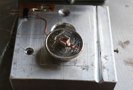
I used my STM to measure the displacement of both an unpoled and a poled actuator. I did this by sticking a small piece of copper tape the top of the actuator and applying the bias voltage (for tunneling) to the tape.
I started scanning the copper tape surface and applied a small 10 Hz sine wave to the MLCC actuator from a function generator. Getting the displacement was then just a matter of reading off the amplitude from the trace/retrace plot during the scan (the Y-axis is in nm):
I measured about ~3 nm/V for the unpoled actuator (or 300 nm over its 100 V range), and ~8 nm/V (800 nm over it’s 100 V range) for the poled actuator. Not too bad, but I had hoped poling would make a bigger difference.
I’m not sure if I’ll build a new scanner using these actuators. They give very little displacement for a given capacitance, but do have the advantages of rigidity and low-cost. Using a smaller package, i.e. 0805 on the Z-axis is a possibility, but the required capacitance would still be fairly high. I might buy some piezo stacks instead, or look for a relatively cheap tube scanner.
That said, MLCC actuators do make for dirt-cheap, rigid nanopositioners, and you can always stack them to get displacements of several microns.


I guess I am too late to the party but couldn´t you use a capacitor array with a lever to increase travel? Attaching a long needle across the top and when you run current through one side of the array that side bulges moving the tip of the needle according to the angle produced between the halves of the capacitor.
LikeLike
Do you mean constructing an array in a single block of piezoelectric material, or from multiple individual capacitors lined up next to each other? You could use a single capacitor and a lever with a flexure pivot, though it might be hard to get a high resonant frequency.
LikeLike
I mean these capacitor arrays. They are multiple capacitors in one.
I had posted a link to a german book series on DIY microscopes but I don´t know where it went. Lots of cool info on micro positioning and other types of microscopes. They have some preview PDFs you could look at.
http://www.rapp-instruments.de/buch/Trilogie/trio.htm
LikeLike
Did you use something like this to generate the high voltage?
http://www.instructables.com/id/High-Voltage-Power-Supply-for-Nixie-and-Valve-Tube/?ALLSTEPS
http://www.instructables.com/id/High-Voltage-Switch-Mode-Power-Supply-SMPSBoost/?ALLSTEPS
Click to access 91053b.pdf
LikeLike
Yup, I used something similar to the first link.
LikeLike
Thanks.
LikeLike
It’s certainly not the best way to do it, but I had some 555s on hand and just wanted to build something up on a breadboard to test the MLCC idea without having to order new components.
LikeLike
Looking forward to your progress. I love the idea of reusing mlcc caps this way.
Can you post the schematic for your boost converter? thanks!
LikeLike
hi,
Congratulations on the STM, with interest I also read this page on mlcc piezo actuators.
I wonder if part of phono cartridges could be used for 2 of the 3 positioning axes?
https://en.wikipedia.org/wiki/Phonograph#Pickup_systems
there are multiple kinds, some should be bidirectional transducers, others rely on resistance measurement. the most common according to wikipedia is
https://en.wikipedia.org/wiki/Magnetic_cartridge
I am under the impression you want stiffness for higher framerates? If we order the response times of the axes, then the highest bandwidth axis should be depth (in constant current mode at least), the second highest bandwidth axis should be the line axis (the one that retraces many times per frame), and the lower bandwidth axis the framerate axis, correct?
I also wondered if one could mill the piezo disc to be shaped like a thin cross, to decrease the coupling with the fluid air?
Another thing I thought about: in alexanders depiction of piezo disc bending, suppose the upwards pointing needle is deflected to the right, then the left cross-section of the disc is depicted as bulging upwards, i.e. concave function, and the right half as convex. To me this seems correct in the case the boundary condition is rotation about a fixed point on the left most point of the cross section and the rightmost point of the cross section. But with glueing or clamping I expect the boundary condition to also fix the slope on the endpoints to horizontal.
So bending the needle to the right, I expect the following from left to right: fixed & horizontal boundary condition.convex,concave,needlebase,convex,concave,fixed & horizontal boundary condition. This suggest subdividing the quadrants electrodes, or the electrodes on a piezo milled to a cross.
Greetings!
LikeLike
Yes, stiffness is crucial for high scan rates and vibration tolerance, and this is most important in the Z-axis.
Milling a piezo disc into a cross would drastically reduce its rigidity, so I don’t see that helping. I think a better solution would be to put it in a vacuum chamber, and pull a mild vacuum (maybe even hand-pumped). This would probably help a lot to reduce acoustic pickup.
By subdividing the electrodes, do you mean diving each quadrant into inner and outer electrodes? It seems to me that this would just introduce two more bends into the disc when actuated and actually reduce travel.
I actually just got a small tube scanner. Managed to find a supplier that sold small quantities (down to single units) and got one for $100, which seemed pretty good.
LikeLike
Maybe you illustrated the principe used in MEMS for actuator, sensor, resonator…
LikeLike
Pingback: Using a Capacitor as an Actuator?! | Hack The Planet
Pingback: Using a Capacitor as an Actuator?! | Ad Pub
Pingback: Using a Capacitor as an Actuator?! | Hackaday